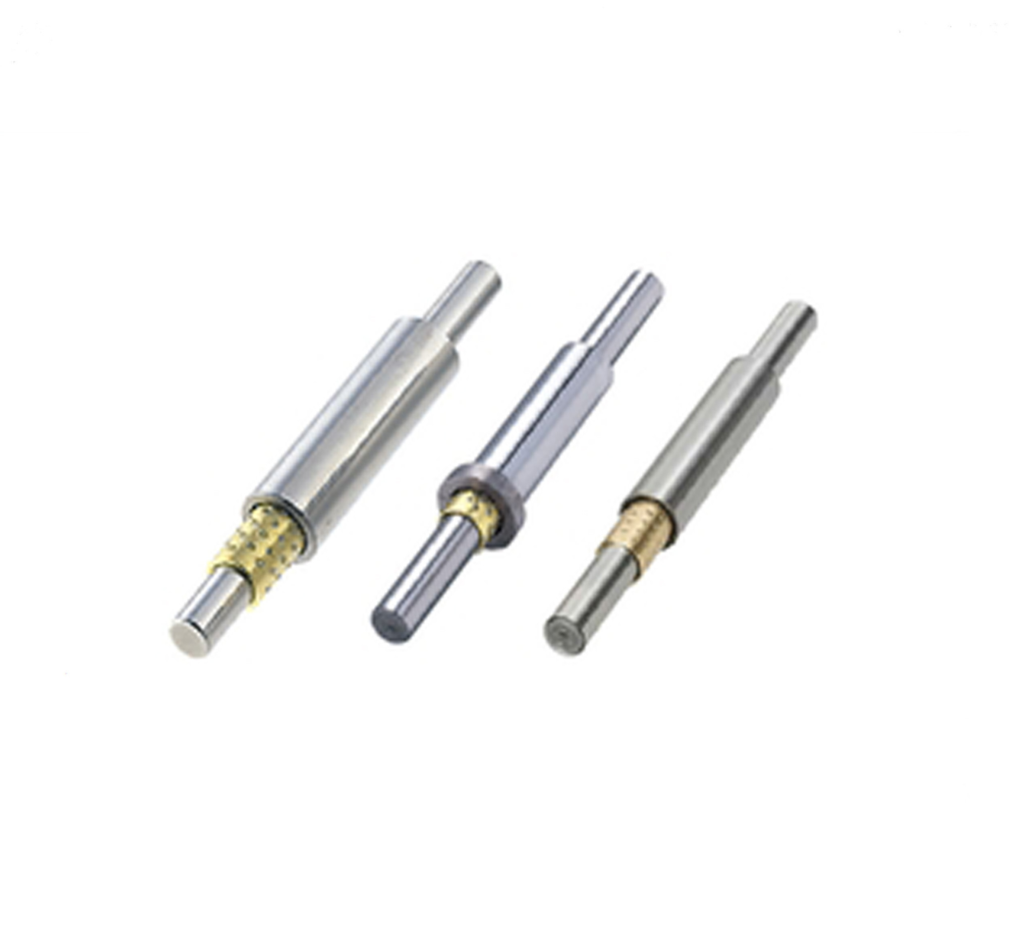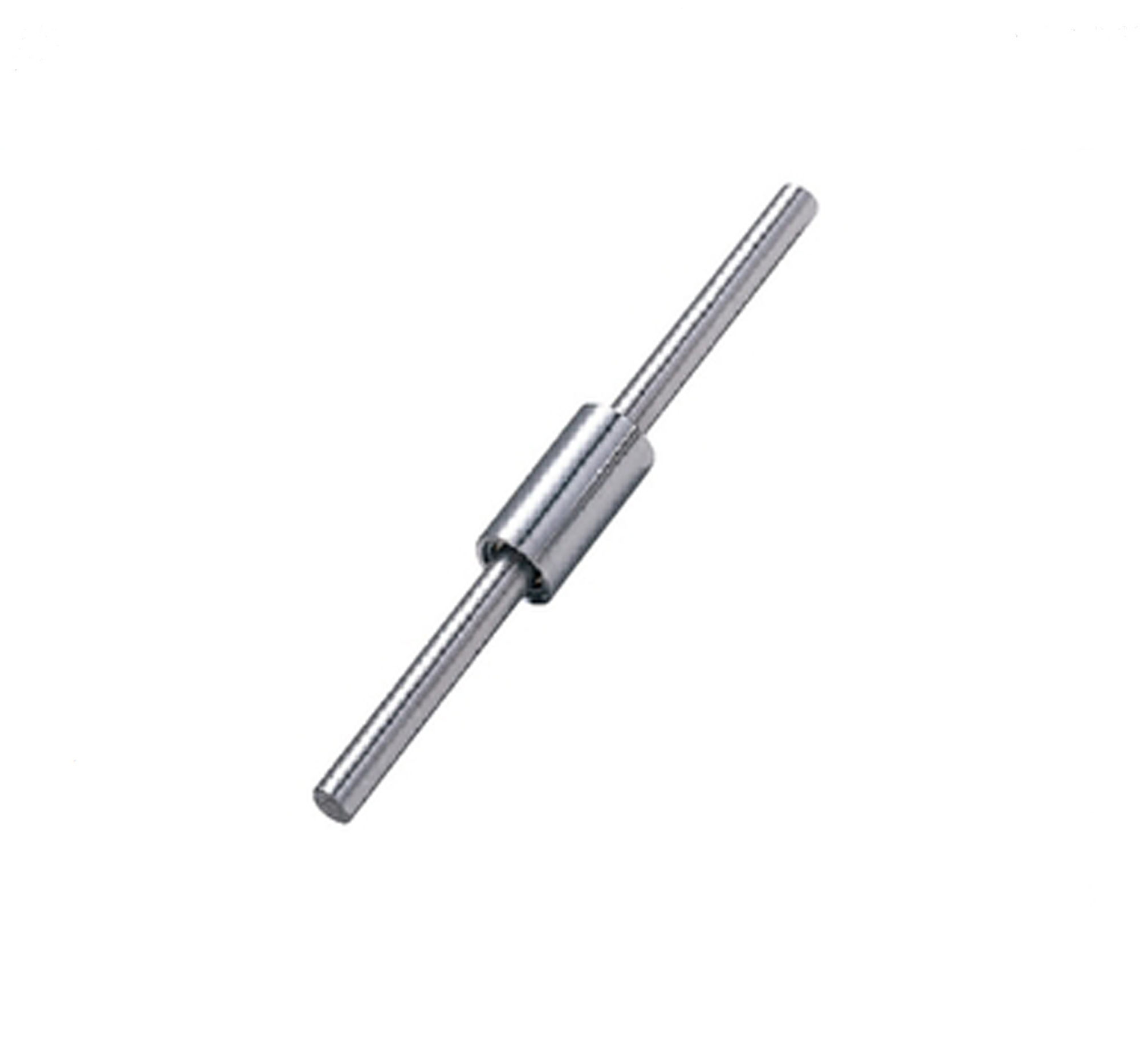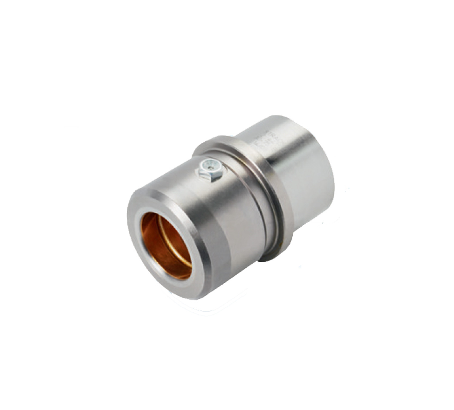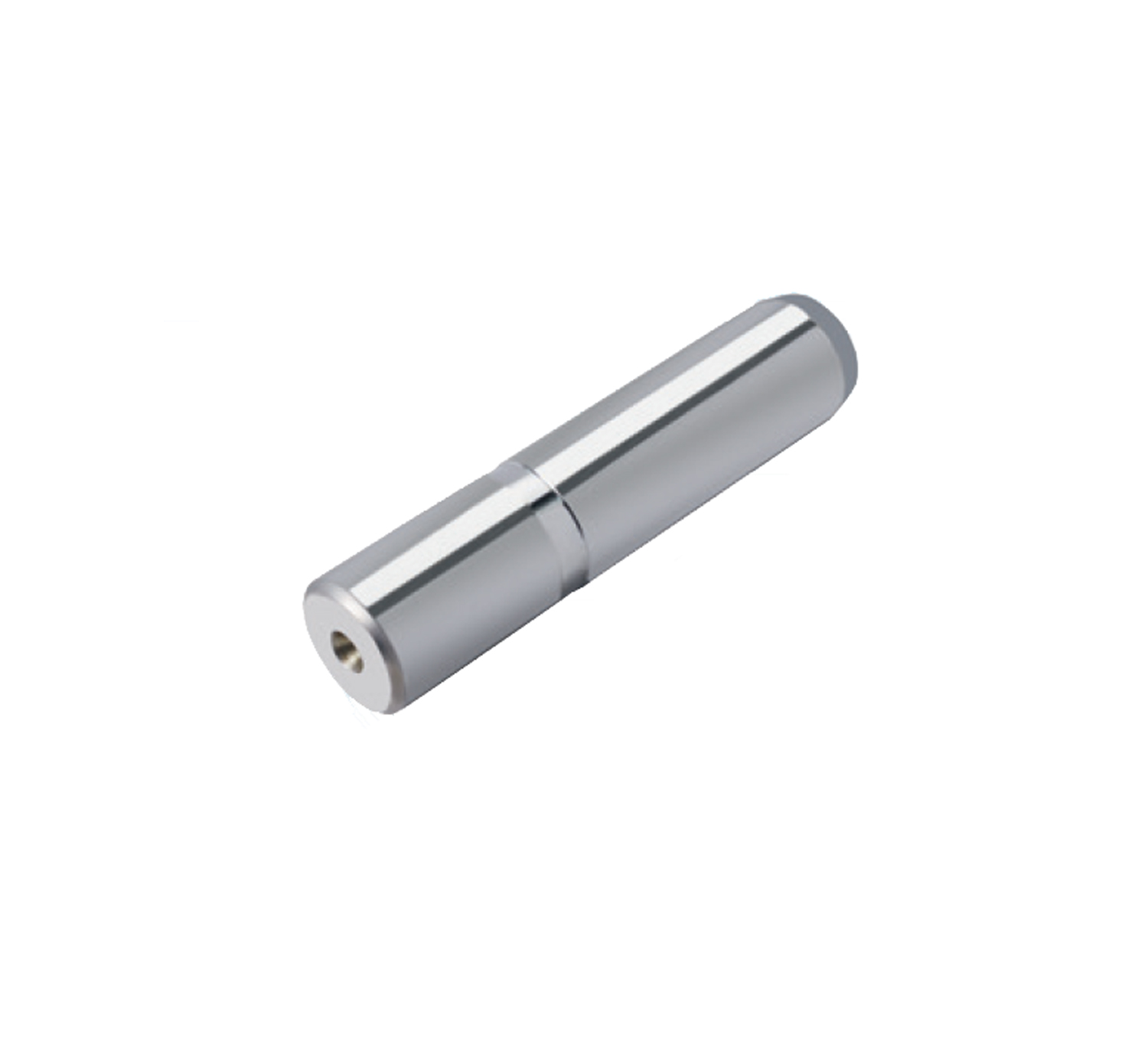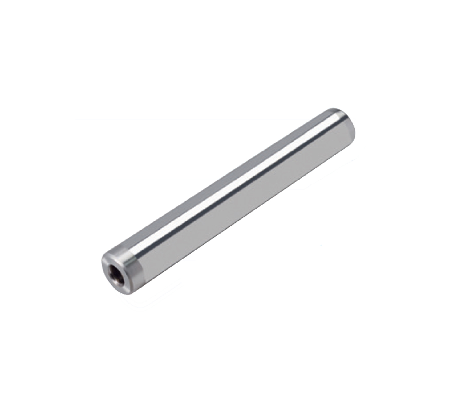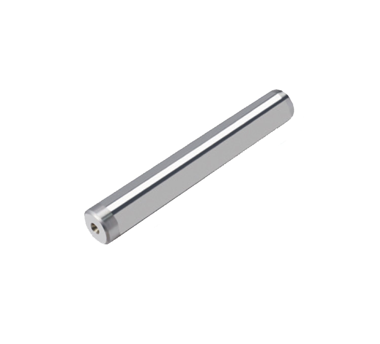
Miniature guide sets, one end tapped hollow
Description
Ask For QuoteProduct item | Miniature guide sets, one end tapped hollow |
Manufacturer | MQ Mold |
Place of origin | Ningbo, China |
Material | Steel |
Hardness | HRC 58-62 |
Mode | Factory & trade |
Type | Material | Hardness | |||||
Type | Bushing | Shafts | Shafts Bushing | Balls Retainer | Steel Balls | Shafts Bushing | Steel Balls |
Both Ends Tapped | |||||||
Standard | Straight type | BGA | 52100 Bearing Steel | JIS C3604 Equivalent | 52100 Bearing Steel | 58 HRC min. | 58 HRC min. |
SSBGA | 440C Stainless Steel Equivalent | 440C Stainless Steel Equivalent | 56HRC min. | 56 HRC min. | |||
Shoulder type | BGHA | 52100 Bearing Steel | 52100 Bearing Steel | 58 HRC min. | 58 HRC min. | ||
SSBGHA | 440C Stainless Steel Equivalent | 440C Stainless Steel Equivalent | 56HRC min. | 56 HRC min. | |||
Compact | Straight type | BYA | 52100 Bearing Steel | JIS C3604 Equivalent | 52100 Bearing Steel | 58 HRC min. | 58 HRC min. |
Shoulder type | BYHA | ||||||
Compact
basic load ratings are lower than standard type for shaft diameter D8 or
smaller>>See Basic Load below
Straight")
Shoulder")
Straight
Part Number | L | Y | F | D1 | T | H | d | M(Coarse Thread) | B | |||
Type | D | Shaft Dia. Tol. | One Ends Tapped Hollow | Selection | Selection |
| Outer Dia. Tol. | |||||
1mm inc. | ||||||||||||
One Ends Tapped Hollow BGA BGHA SSBGA SSBGHA | 5 | 0 | 40-90 | 10 20 30 | 10 15 20 | 10 | 0 | 3 | 12 | 7 | M3 | 1.0 |
6 | 20 30 40 | 15 20 30 | 11 | 0 | 4 | 13 | 8 | M3 | ||||
8 | 40-150 | 12 | 14 | 10 | M4 | |||||||
10 | 30 40 50 | 20 30 40 | 16 | 18 | 12 | M5 | ||||||
12 | 18 | 20 | 14 | M6 | ||||||||
1. When designing, it is recommended to position the bushing to prevent the ball slider from falling
2. Calculate the stroke as "(Y-F)x2". The stroke of bushing or shaft is twice as much as the travel distance of ball slider (Y-F).
Compact
Part Number | L | Y | F | D1 | T | H | d | M(Coarse Thread) | B | |||
Type | D | Shaft Dia. Tol. | One Ends Tapped Hollow | Selection | Selection |
| Outer Dia. Tol. | |||||
1mm inc. | ||||||||||||
One Ends Tapped Hollow L Dimension Configurable BYA BYHA | 5 | 0 | 40-90 | 10 20 30 | 10 15 20 | 8 | 0 | 3 | 10 | 6.2 | M3 | 0.6 |
6 | 20 30 40 | 15 20 30 | 9 | 0 | 4 | 11 | 7.2 | M3 | ||||
8 | 40-150 | 11 | 13 | 9.2 | M4 | |||||||
10 | 30 40 50 | 20 30 40 | 14 | 16 | 12 | M5 | 1.0 | |||||
12 | 16 | 18 | 14 | M6 | ||||||||
1. When designing, it is recommended to position the bushing to prevent the ball slider from falling
2. Calculate the stroke as "(Y-F)x2". The stroke of bushing or shaft is twice as much as the travel distance of ball slider (Y-F).
Basic Load Rating List
D | F | Basic Load Rating | |
Co(Static) N | |||
Standard | Compact | ||
5 | 10 | 50.7 | 26.1 |
15 | 84.5 | 42.4 | |
20 | 109.9 | 58.7 | |
6 | 15 | 101.5 | 43.2 |
20 | 113.2 | 59.8 | |
30 | 182.9 | 83.1 | |
8 | 15 | 105.1 | 59.0 |
20 | 126.1 | 81.6 | |
30 | 189.2 | 113.4 | |
10 | 20 | 147.7 | 147.7 |
30 | 221.5 | 221.5 | |
40 | 307.7 | 307.7 | |
12 | 20 | 187.4 | 187.4 |
30 | 281.1 | 281.1 | |
40 | 390.5 | 390.5 | |