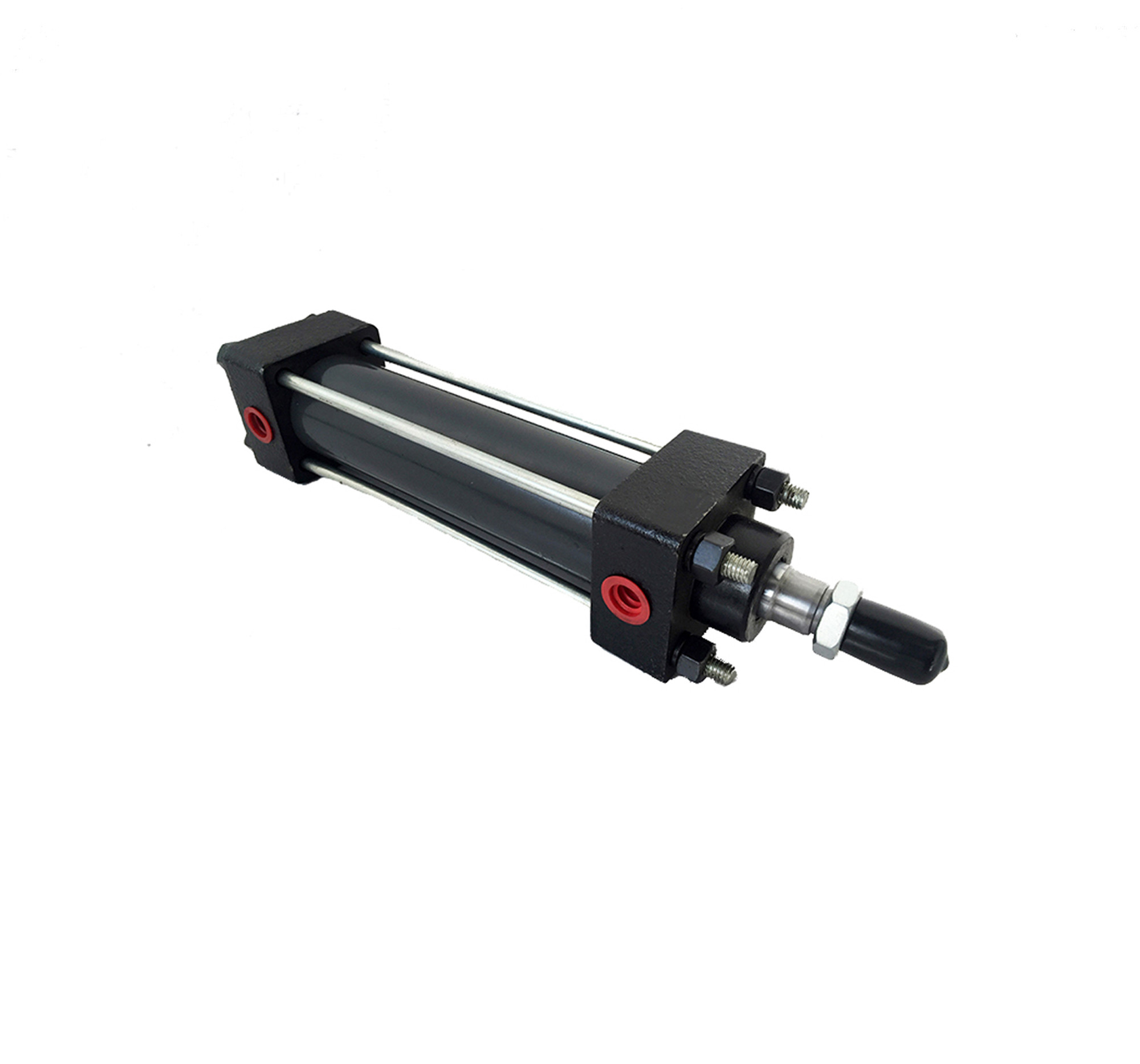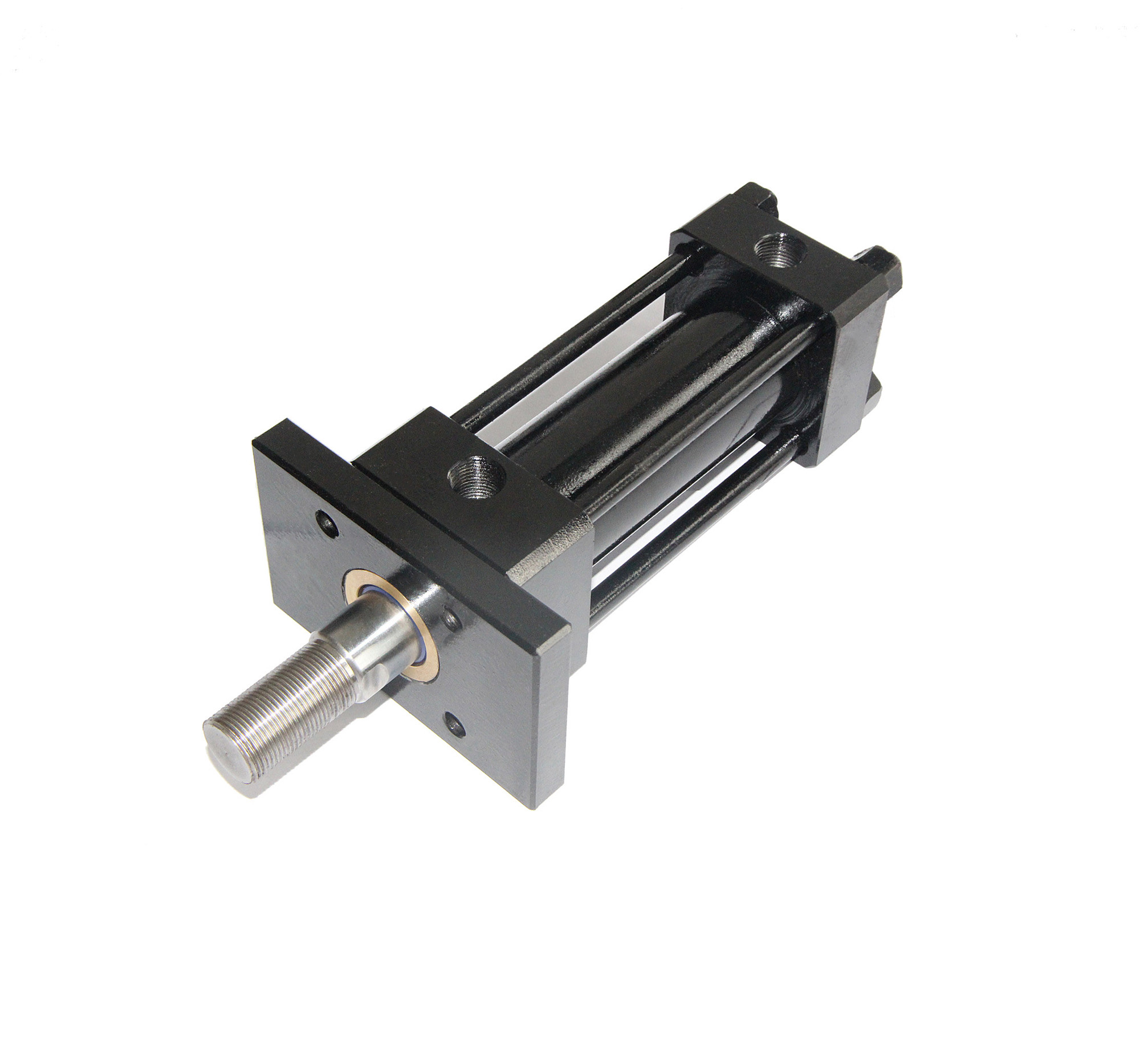
HOB tie rod cylinder
Description
Ask For Quote HOB tie rod cylinder is the hydraulic execute component, which could transform hydraulic energy into mechanical energy, realizing straight reciprocating motion or rocking motion.
With features of simple structure and reliable operation, while reciprocating motion, it could save the speed reducer, no transmission clearance, and keep stable motion. So the tie rod hydraulic cylinders have been widely applied in hydraulic system of various machine. Output force of the cylinder is in direct proportion to active area of the piston and the difference value between the two sides.
According to different using environments, the specification for tie rod cylinder could be customized. They are assembled by hand of highly specialized personnel, and measured against strict tolerances. After finished, 100% test for the products, and then pack up to leave factory.
Product name | HOB tie rod cylinders |
Item No. | / |
Manufacturer | MQ Mold |
Place of origin | Ningbo, China |
Material | / |
Hardness | / |
Mode | Factory & trade |
| Code | Name | Drawing | Code | Name | Drawing |
| SD | Basic | ") | FA | Head-mounted | ") |
| LA | Foot mount | ") | FB | Cap-mounted | ") |
")
")
")
Cylinder dia. | D | L | W | G | HA | HB | RA | RB | P1(PT) | EH | H | H1 | M1 | M2 | NB | NC | ND | NE | R | N | U | V |
32 | 20 | 17 | 17 | 11 | 38 | 26 | 25 | 13 | 3/8 | 10 | 25 | 20 | M12 | M16 x 1.5 | 20 | 10 | 8 | 8 | 1 | 2 | 35 | 14 |
40 | 25 | 22 | 22 | 17 | 38 | 28 | 25 | 14 | 3/8 | 12 | 40 | 25 | M14 | M20 x 1.5 | 25 | 13 | 10 | 10 | 1 | 3 | 40 | 8 |
50 | 30 | 27 | 27 | 18 | 42 | 34 | 27 | 19 | 3/8 | 13 | 40 | 25 | M16 | M26 x 1.5 | 30 | 16 | 13 | 13 | 1 | 3 | 46 | 10 |
63 | 35 | 32 | 32 | 20 | 42 | 34 | 27 | 19 | 3/8 | 14 | 45 | 25 | M18 | M30 x 1.5 | 35 | 22 | 16 | 16 | 2 | 3 | 55 | 9 |
80 | 40 | 36 | 36 | 24 | 46 | 40 | 28 | 22 | 3/8 | 16 | 45 | 25 | M20 | M30 x 1.5 | 40 | 30 | 20 | 20 | 2 | 4 | 65 | 8 |
100 | 50 | 45 | 45 | 28 | 50 | 45 | 30 | 25 | 1/2 | 18 | 55 | 30 | M22 | M40 x 2.0 | 50 | 35 | 30 | 30 | 2 | 4 | 80 | 6 |
125 | 60 | 55 | 55 | 33 | 58 | 53 | 30 | 28 | 3/4 | 18 | 70 | 30 | M24 | M50 x 2.0 | 60 | 40 | 30 | 30 | 2 | 4 | 95 | 8 |
Cylinder dia. | SD | FA/FB | LA | ||||||||||
T | A | K | AA | BB | TA | TB | FC | LA | LT | LB | LD | LC | |
32 | 40 | 55 | M10 | 109 | 63 | 88 | 40 | 11 | 109 | 88 | 63 | 14 | 11 |
40 | 45 | 65 | M10 | 115 | 75 | 93 | 50 | 12 | 112 | 90 | 69 | 14 | 12 |
50 | 56 | 80 | M12 | 150 | 85 | 110 | 56 | 13 | 140 | 115 | 85 | 17 | 14 |
63 | 65 | 95 | M14 | 155 | 100 | 126 | 68 | 14 | 156 | 128 | 100 | 19 | 14 |
80 | 80 | 110 | M16 | 190 | 120 | 152 | 75 | 18 | 184 | 152 | 115 | 25 | 18 |
100 | 95 | 131 | M18 | 220 | 140 | 180 | 100 | 20 | 210 | 178 | 137 | 27 | 21 |
125 | 122 | 162 | M22 | 280 | 170 | 222 | 122 | 24 | 280 | 230 | 171 | 30 | 24 |
Pressure | Type | DD | ST( 1mm) | C(1mm) | Shape of piston rod | Heat resistance | Installation way |
M | |||||||
140kgf/cm2 | Compact hydraulic cylinder | 32 | 5~500 | 30~150 | IN IS IT | N(-5℃~80℃) | SD |
40 | |||||||
50 | |||||||
63 | 35~150 | ||||||
80 | |||||||
100 | 40~150 | ||||||
125 | 45~150 |